
Share with AI
Open this article in your assistant
Ask ChatGPTAsk PerplexityAsk ClaudeAsk GeminiAsk DeepSeekAsk GrokBMW E60 Fan Activation Strategy | Bosch EDC16 WinOLS & ECM Titanium Guide
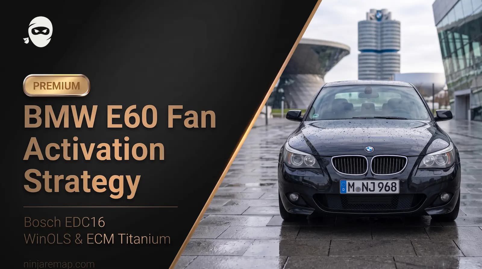
The BMW E60 5 Series is one of the most popular diesel platforms for ECU tuning. Models equipped with the M57 engine, particularly the 525d and 530d, offer excellent tuning potential thanks to their inline six-cylinder design, Common Rail direct injection system, and Variable Geometry Turbocharger (VGT). Depending on the engine variant, the factory power output ranges from 163 to 231 horsepower. However, what truly makes the M57 stand out is its impressive torque, which can easily exceed 500 Nm with a properly calibrated Stage 1 or Stage 2 tune.
As boost pressure and fuel delivery are increased during Stage 1 and Stage 2 tuning, the engine's thermal load rises significantly. In turbocharged diesel engines, heat is typically concentrated around the turbocharger, cylinder head, and when present, the EGR and DPF systems. For this reason, proper cooling system management is not merely a secondary consideration; it is a key factor in maintaining engine reliability and long term durability in tuned applications.
Many tuners focus primarily on boost maps, torque limiters, and injection duration, while leaving the radiator fan control strategy unchanged. However, this cooling strategy is equally important for supporting the additional power and heat generated by performance tuning. This is where the Fan Activation map becomes particularly important.
Introduction to the Bosch EDC16 ECU:
In diesel-powered BMW E60 models equipped with the M57 engine, engine management is typically handled by the Bosch EDC16 ECU.
This ECU is based on a torque-based control strategy and is responsible for managing the engine's critical functions, including fuel injection timing and duration, rail pressure control, VGT turbocharger management, EGR operation, and also DPF regeneration.
One of the major differences between this generation of ECU and older engine management systems is the way the radiator fan is controlled. In many older vehicles, the cooling fan simply operated in an ON/OFF manner. In contrast, the Bosch EDC16 controls the fan using a PWM (Pulse Width Modulation) signal, allowing the ECU to regulate fan speed progressively according to the engine's thermal conditions.
The ECU continuously monitors parameters such as coolant temperature, vehicle speed, air conditioning status, engine load, and even the DPF operating condition. Based on these inputs, it calculates the appropriate fan Duty Cycle and transmits it to the fan control module via a PWM signal.
As a result, fan operation is governed by a predefined strategy stored within the ECU calibration file rather than being a simple reaction to a single coolant temperature threshold. Understanding this control architecture is essential before modifying the Fan Activation map.
How to Read and Write the Bosch EDC16 ECU?
A complete ECU read must first be obtained, before analyzing or modifying the Fan Activation map.
Depending on the software version, the Bosch EDC16 installed in these vehicles can be accessed via OBD, Bench Mode or Boot Mode.
Common professional tools used to read and write this ECU include:
- KESS
- KTAG
- CMD Flash
- Autotuner
A complete backup (Full Read) containing both the Micro and Flash sections is highly recommended before making any modifications, ensuring the ECU can be fully restored if necessary.
Once the original file has been extracted, it is typically analyzed using software such as WinOLS or ECM Titanium.
Within WinOLS, identifying maps such as the Fan Activation table requires recognizing the logical axis structure, identifying the increasing temperature breakpoints, and correctly interpreting the PWM output values using the proper scaling factors.
These tables typically contain predefined temperature breakpoints that determine how the cooling fan behaves under different operating conditions.
Cooling System Architecture and Fan Control Strategy in the Bosch EDC16:
In the BMW E60 diesel equipped with the M57 engine, the cooling system consists of much more than just the radiator and cooling fan. These components are only part of the engine's overall thermal management strategy. In turbocharged diesel engines, especially those with performance tuning, effective temperature control is critical, as increased boost pressure and higher fuel delivery directly increase the engine's thermal load.
On this platform, the cooling system consists of several components, including:
- Main radiator
- Water pump
- Electronically controlled thermostat
- Electric cooling fan
- Auxiliary heat exchangers for the EGR system and other supporting systems
Unlike many older vehicles where the cooling fan simply switched on and off at a predetermined temperature, the Bosch EDC16 manages the fan using an intelligent, multi-stage control strategy. The ECU continuously monitors the engine's operating conditions and determines the appropriate fan speed based on the current thermal load.
The primary parameters involved in this decision include:
- Coolant temperature
- Vehicle speed
- Engine load and generated torque
- Air conditioning (A/C) status
- DPF regeneration and post-injection conditions
Fan speed is controlled using a PWM (Pulse Width Modulation) signal. PWM allows the ECU to regulate fan speed and cooling capacity without directly changing the supply voltage.
In practice, the ECU adjusts the PWM Duty Cycle to determine how fast the cooling fan should operate. A higher Duty Cycle results in higher fan speed and greater cooling capacity, while a lower Duty Cycle keeps the fan running at a lower speed. As the PWM Duty Cycle increases, the cooling performance rises accordingly.
Because PWM operates at a very high frequency, the fan speed changes smoothly and progressively, eliminating the abrupt ON/OFF behavior found in older cooling systems.
Using PWM offers several important advantages over traditional on/off fan control. It allows the ECU to regulate engine temperature much more precisely while minimizing large thermal fluctuations. The gradual increase in fan speed also prevents sudden electrical loads on the charging system and alternator, reducing stress on electrical components and lowering fan noise.
Overall, progressive fan control improves both energy efficiency and the overall performance of the cooling system.
In the Bosch EDC16, the fan control strategy is defined directly within the ECU calibration file. Dedicated calibration maps determine the PWM Duty Cycle that should be applied under different operating and temperature conditions.
An important point is that fan operation is not determined solely by coolant temperature. Under certain conditions, vehicle speed and engine thermal load also influence the ECU's decision. As a result, the behavior of the Fan Activation map may initially appear counterintuitive.
For example, why does the ECU sometimes command a high fan Duty Cycle even at high vehicle speeds, where the airflow through the radiator is already significantly increased? Is this strategy simply compensating for airflow, or is it part of the ECU's engine protection logic?
At first glance, it may seem logical that higher vehicle speeds should allow the ECU to reduce the fan Duty Cycle because of the increased ram air passing through the radiator. However, in practice, if the engine continues to operate at coolant temperatures between 110°C and 118°C while traveling at high speed, the ECU interprets this as a high thermal load rather than insufficient airflow.
Under these conditions, boost pressure, turbocharger temperature and exhaust gas temperature (EGT) are typically elevated as well. Consequently, the ECU enters a protective operating strategy and maintains maximum cooling capacity to prevent heat soak and excessive temperatures throughout the engine and turbocharger assembly.
Analyzing the Fan Activation Map in ECM Titanium and Identifying It in WinOLS:
Now that we understand the cooling system architecture and the PWM control strategy, we can examine the Fan Activation map itself.
The image shown below illustrates this map in ECM Titanium, where the calibration values are presented in an intuitive engineering format.
In this map, the horizontal axis represents the coolant temperature, while the vertical axis corresponds to different vehicle speed conditions. The values within the table represent the fan PWM Duty Cycle (%).
At first glance, it is clear that up to approximately 100°C, virtually no fan activity is commanded, as all table values remain at 0% Duty Cycle.
This behavior is entirely normal. Within the normal operating temperature range, the ECU relies primarily on the engine's mechanical cooling system and the natural airflow passing through the radiator before activating the electric cooling fan.
With the purchase of this article:
- You will learn the Fan Activation Strategy in the BMW E60 (EDC16 ECU), and we will analyze a real file with real values using WinOLS and ECM Titanium.
- You will also receive the original file and the MapPack for this vehicle and ECU with premium section of the article.
 Premium ContentUnlock this section to read the full guide.
if you encounter any issues during the article purchase process, feel free to contact us viaWhatsAppor NinjaRemapEmail.